Tolerance is the minimum and maximum limit within which a dimension could exist on a physical part. It is nearly impossible to create a physical part meeting the exact dimensions, hence a tolerance is specified in the drawing / CAD data to let the operator know the dimension limits. Also, the manufacturing cost is directly proportional to the tolerance required. The closer the tolerances, the higher will be the cost and vice versa. During the inspection, if the manufactured part is found to be beyond the defined limit, it is entirely rejected or sent to rework.
Tolerances in CNC machining
Generally, there are two types of tolerances used in CNC machining, one w.r.t to tolerance capability of the CNC machine and the second is the dimensional tolerance limit within which the dimensional parameter could exist. Tolerance w.r.t to CNC machine means the minimum tolerance or accuracy of the dimensional parameters that the CNC could achieve. Nowadays, with the advancement of technology, certain special CNC machines can achieve part dimensional accuracy within 10 microns. Generally available CNC machines, on average, can achieve an accuracy of around 25 microns. CNC machine manufacturers specify the accuracy achieved by their machines in the technical specification guide.
Tolerances in product design are defined by the product designer within which the dimensional parameter should exist in order to be acceptable. Part dimensional tolerances are determined by the designer according to the application, fitment and overall form of the design. Dimensional accuracy is more significant in a multi-part assembly where different parts are mating with other components. For example, a car engine is an assembly of multiple individual components such as shafts, pistons, and valves, and each part is manufactured to the closest possible tolerance to achieve desired performance requirements. Engine parts are made with much tighter tolerances than a hand brake handle because the performance requirements of engine parts are much higher than the hand brake handle. Part tolerance is generally captured closer to the concerned dimensions in the drawing and as a 3D annotation in the CAD file of the part.
Type of tolerances
- Limit tolerance
- Unilateral tolerance
- Bilateral tolerance
- GD&T method
Limit tolerance
Limit tolerances specify upper and lower limits of dimensional variation. Any measurement beyond the specified limit is considered invalid and the part is rejected. For example, 10mm +0.5/-0.25 dimension on a part means the upper limit is 10.5mm and the lower limit is 9.75mm. The final dimension of the manufactured part should be between 9.75 to 10.5mm to qualify for the inspection process else the part is rejected or sent for rework.

Limit tolerance
Unilateral tolerance
Unilateral tolerance is defined as the dimensional variation in either the upper or lower direction. For example, 10mm +0.5/0.00 means the variation is permitted only in a positive direction only. Hence, the dimension of the produced part should lie between 10.00 to 10.5mm only to qualify for the inspection process.

Unilateral tolerance
Bilateral tolerance
Bilateral tolerance means the upper and lower limit varies uniformly about the dimension value. For example, 10mm +/- 0.5mm means the dimensional value of the manufactured part should lie between 9.5mm to 10.5mm to qualify for the inspection process.

Bilateral tolerance
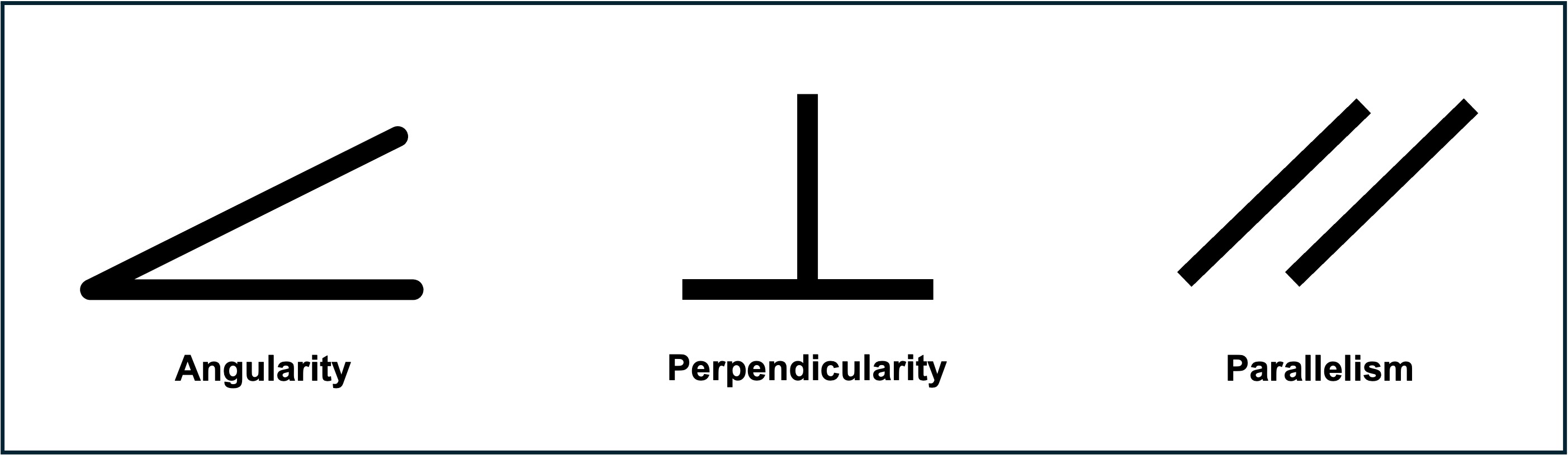
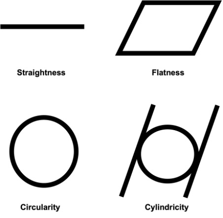
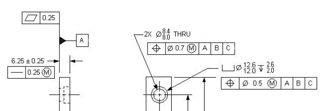
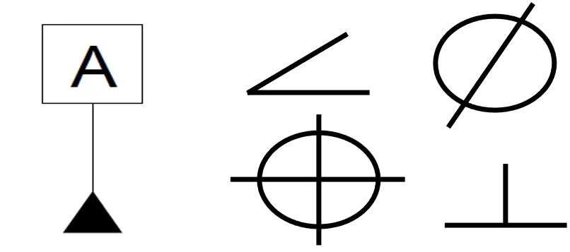
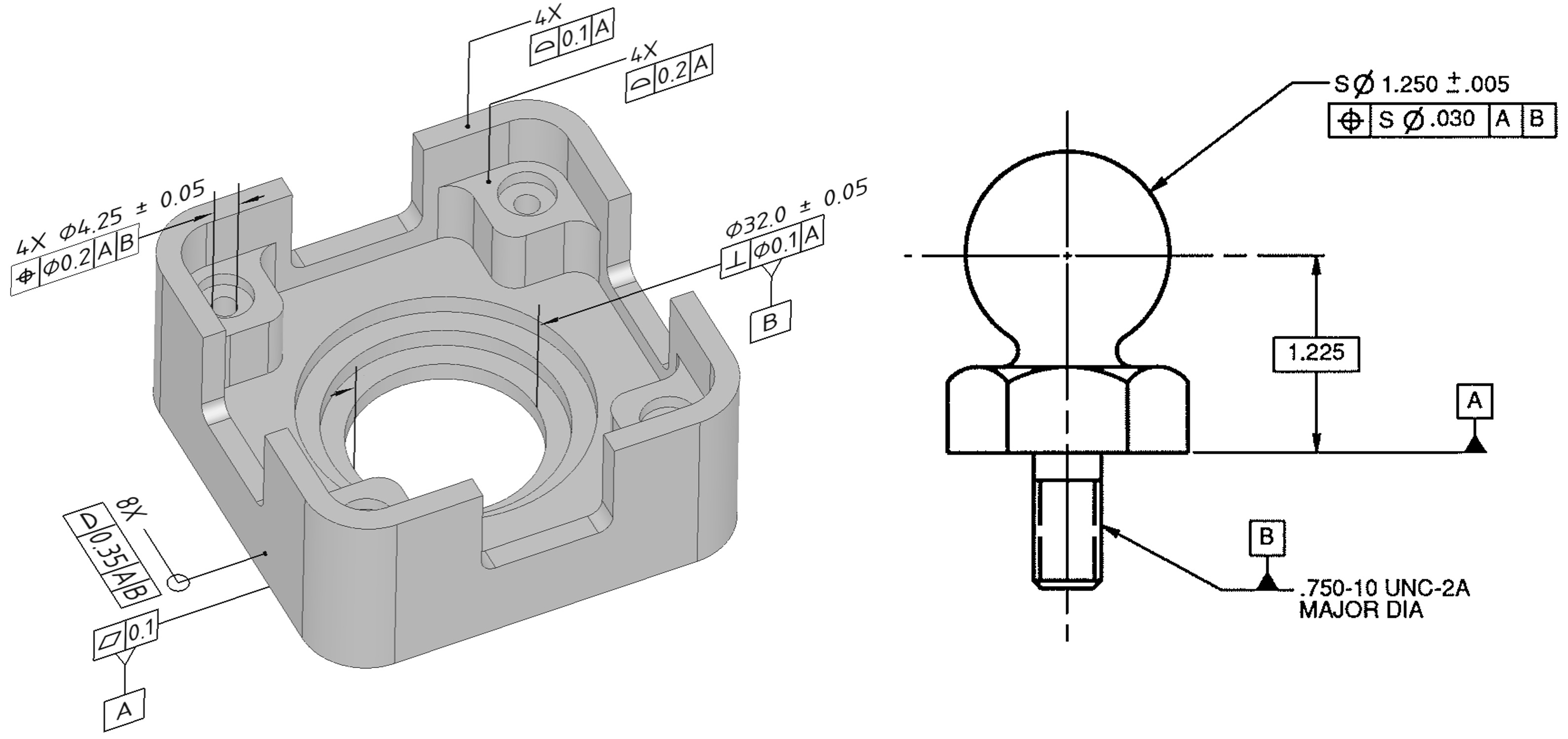
GD&T method
GD&T is the standardized system of dimension and tolerances which is slightly more complex but much superior to other methods. Apart from dimensions and tolerances, GD&T notations also provide geometric properties of the part feature such as circularity, cylindricity, flatness etc. for which the tolerance value is given.

GD&T
Tolerancing key points
There are certain important points that a designer needs to remember while creating the GD&T/tolerances for the part.
- Every feature doesn’t need tolerances. Apply tolerances wherever necessary and important from the application point of view. This will save the machining cost and lead time.
- Designers need to understand the CNC machine tolerance capability prior to applying tolerances. If the applied tolerance is beyond the machine's capability, then, the designer should loosen the tolerance value or look for compatible machines.
- Designers should refrain from applying too tight tolerances unless needed otherwise the cost of manufacturing will go up substantially. May require special fixtures, and tools to verify the dimension adding up to the cost of production.
- While applying tolerances, designers need to understand process/machine capabilities and material properties. Tighter tolerances may not work for flexible/softer materials like ABS, Delrin, nylon etc.