Uniform wall thickens
Generally, thinner walls are more feasible with smaller parts rather than with large ones. The limiting factor in the wall thickness is the tendency for the plastic material in thin walls to cool down and solidify before the mold is filled. The shorter the material flow, the thinner the wall can be. Walls also should be as uniform in thickness as possible to avoid warpage from uneven shrinkage.
|
MATERIAL |
RECOMMENDED THICKNESS (mm) |
|||
|
SHORT SECTIONS |
SMALL SECTIONS |
AVERAGE SECTIONS |
LARGE SECTIONS |
|
|
PP |
0.6 |
0.9 |
1.9 |
3.2 - 4.7 |
|
ABS |
0.9 |
1.3 |
1.9 |
3.2 - 4.7 |
|
NYLON |
0.3 |
0.6 |
1.5 |
2.4 – 3.2 |
|
PC |
0.4 |
0.8 |
1.8 |
2.4 – 3.2 |
|
ACRYLIC |
0.6 |
0.9 |
2.3 |
3.2 – 6.3 |
|
PVC (RIGID) |
0.9 |
1.6 |
2.4 |
3.2 – 4.7 |
|
PS |
0.8 |
1.3 |
1.6 |
3.2 – 6.3 |

Hollow sections
Core out the thick sections as shown to maintain a more uniform wall thickness.

Gradual surface transition
maintain uniform wall thickness as far as possible, and if changes in wall thickness are unavoidable, make them gradual rather than abrupt.

Holes and weld lines
Holes are feasible in injection molded parts but are a complication factor in mold construction and part quality. Weld lines are adjacent to the hole often develop and flashing also may occur at the edge of the hole.
Minimum hole spacing between two holes or between a hole and sidewall should be one diameter.
- Thru-hole is preferred over blind hole because core pin that produces hole can be supported at both ends.
- Holes in the bottom part are preferable to those in the side because the latter require retractable core pins.
- Blind holes should not be deep more than two times the diameter.
- if the diameter is 1.5mm or less, one diameter is the maximum practical depth

To increase the depth of a deep blind hole, use steps. This enables a stronger core pin to be employed

Ribs
Ribs are added to reinforce the wall/design against the load/forces.
- Recommended rib thickness should be 0.4 to 0.6 of wall thickness.
- Ribs should not be higher than 2.5 to 3.0 times the wall thickness.
- Ribs should have a generous draft of 0.5˚ to 1.5˚ per side.
- There should be a radius of 25% to 40% of wall thickness(wt)
- The rib should be two or more wall thicknesses apart for better design
- The rib should be perpendicular to the parting line in order to permit removal of the part from the mold
- Reinforcing ribs should be thinner than the wall they are reinforcing to prevent sink marks opposite side
- Two ribs may be used, if necessary, to provide the extra reinforcement that would otherwise be provided by a high rib


Under-cuts
An undercut is a projection that prevents part ejection from a mold.
- Undercuts are possible with injection-molded thermoplastics parts, but they may require sliding cores or split molds
- External undercuts can be placed at the parting line or extended to the line to obviate the need for core pulls
- Shallow undercut often may be strippable from mold without the need for core pulls
- Shallow undercuts often may be strippable from the mold without the need for cores pulls
- Undercuts can often be stripped from the mold if its size is within the guidelines for the type of material used


Inserts
Inserts are useful and practical to provide reinforcement where stresses exceed the strength of the plastic material.
Sharp corners should be avoided on the portion of the insert that is immersed in the thermoplastics.
Knurls on machined inserts should be relatively coarse to permit the material to flow into the recesses.


Ample supporting material must be provided around an insert
Bosses
Bosses are the protruding pads used to provide mounting surfaces or reinforcements around holes.
- If large bosses are needed, they should be hollowed for uniformity of wall thickness
- Excessively long bosses can be replaced by 2 shorter bosses
- Bosses in the upper portion of the mold can trap gases and should be avoided
- If possible, locate bosses in corners to aid material flow in filling the mold
- If a detached boss is necessary, a connecting rib will aid material flow
If the diameter of the insert is 6mm or less, the boss diameter should be at least twice that of the insert

Threads
- Threads use a core that is rotated after the molding cycle has been completed. This unscrews the part from the mold.
- Put the axis of the external screw parting line of the mold, avoiding the need for a rotating core but necessitates a very good fit between mold halves to avoid flash across the threads (omit threads in the area of parting line).
- If threads with strong holding power are needed, then use metal inserts.
- Internal threads can be tapped in almost all thermoplastics, and if the thread diameter is 5mm or less, tapping is economical than molding.
- Self-tapping screws are preferable to molded threads and conventional screws.
- Make the threads a few, shallow, and rounded forms so that the part can be stripped from the mold without unscrewing.
- A coarse thread with a somewhat rounded form is preferred for all screw threads because of ease of filling and avoidance of feather edges even if it is removed by unscrewing.

Lettering
- It is desired to have depressed letters on the part and to fill them with paint that contrasts with the color of the plastic material.
- Cavities for filled lettering should be sharp-edged and 0.13 to 0.18mm wide.
- The depth should be one half of the width and rounded at the bottom.

Draft
- It is highly desirable to incorporate some draft, in the sidewalls of injection molded parts to facilitate removal of the part from the mold.
- Drafts as low as ¼ degree are adequate
- Usually, deep parts require less draft angle than shallow parts
- For shallow parts, draft should average ½ deg or more
- For deep parts, 1/8 deg can often be satisfactory
- Textured surfaces require greater drafts

Radius and fillets
- Fillets and radius should be as generous as possible
- Sharp corners should be avoided except at the parting line
- They interfere with the smooth flow of material and create possibilities for turbulence which results in surface defects. Sharp corners also cause stress concentrations in the part that are undesirable from a functional point of view
- A desirable minimum under any circumstances is 0.5mm, while 0.1mm is a part preferable minimum if part requirement permits.
Surface finish
- Surface polish or textures can be molded into the part
- No secondary surface-finishing operations are necessary (except plating, hot stamping, or painting is desired)
- High-gloss finishes are feasible if the mold is highly polished and if molding conditions are correct
- However, dull, matte, or textured finishes are preferred to glossy finishes, which tend to accentuate sink marks and other surface imperfections.
- Painting of most thermoplastics is feasible but is not recommended if the colour can be molded into the part.
- The latter approach obviously is more economical and gives superior results.
- If contrasting colours are required, masks can be fabricated and a portion of the part left unpainted.
Mold parting line
- Every injection-molded part shows the effect of the mold parting line, the junction of the two halves of the mold.
- The part (and the mold) should be designed so that the parting occurs in an area where it does not adversely affect the appearance or function of the part.
- One way to do this is to put the parting line at the edge of the part where there is already a sharp corner.
- Surface decorations like flutes, reeds and textures should stop short of the parting line so the flash is easy to remove.
- If possible, put the mold parting line at the edge of the part.
- If not, possible to place the parting line at the edge of the part, a bead or other raised surface is recommended at the parting line to facilitate the cleaning of the parting line flash.
- Parting lines should be straight, i.e., the two mold halves should meet in one plane only.
- This obviously provides more economical mold construction, but it may not be possible if the part design is irregular.
- If it is not possible to place the parting line at the edge of the part, the cleaning parting line flash is facilitated by having a bead or other raised surface at the parting line.

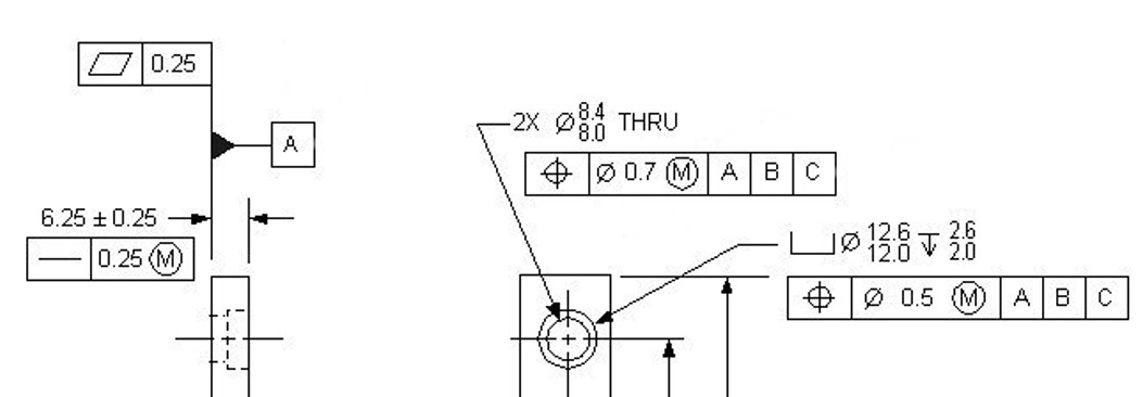
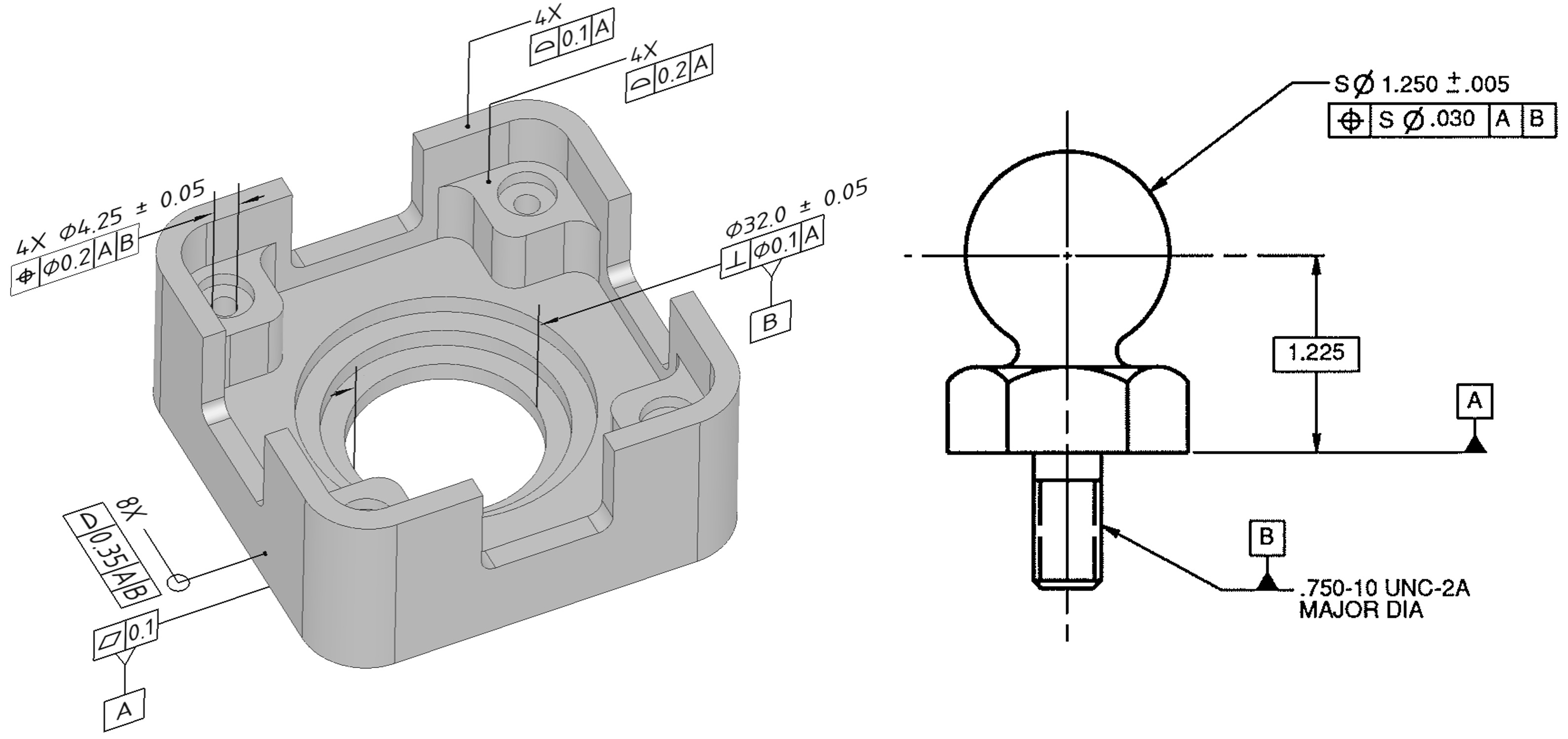
Tolerances
Dimensions cannot be held to the precision on a closely tolerated mold due to the following reasons:
- Plastic material’s shrinkage, including its variation and unpredictability.
- High thermal coefficient of expansion of plastics.
- Despite automatically controlled apparatus for pressure, temperature, and time settings, there is some variation in these factors from cycle to cycle, resulting in slight dimensional variations in molded parts.
- Mold runners, cooling channels, and gates cannot always be in the optimal position, leading to differences in how uniformly the material in ”packed” in the mold and how uniformly it cools.
- Some distortion or built-in stresses are unavoidable.
- Plastic parts, when assembled, often can be deformed slightly if this is necessary to ensure a good fit.
- Skilled designers take advantage of the flexibility factor of plastics by designing lips and locating bosses on plastic parts to alignment with mating parts.
- Close dimensional tolerances can greatly increase the cost of injection-molded parts.
- Finely tolerated molds are costlier than loosely tolerated molds.
- Processing cost increases when extra tight dimensional control is needed for example,
- Closer process controls are needed for pressure, temperature, and cycle time
- Cycle time may be increased
- Shrink fixture may be required to control dimensions of the part after removal from mold
- Higher rejection rates are likely.
- Different plastics materials have different tolerance capabilities
- Low-shrinkage materials can invariably be molded with closer tolerances
- Glass or mineral-filled materials can be molded more accurately than unfilled materials
- The use of a greater number of mold cavities tends to reduce the closeness of dimension control over the molded parts.
- As a rule of thumb, for each cavity after the first, allowable dimensional tolerances should be increased by 5%