Main causes of IM defects
- Material (thermoplastics)
- Injection molding machine
- Molding tool
- Product design
Material
The material factor that causes defects are
- Granule type and its size
- Plastic grade - Easy flow & Hard flow
- Moisture absorption - Pre-heating time
Injection molding machine
Molding machine factor that causes defects are
- Selection of machine with sufficient capacity - Shot capacity, Plasticizing capacity & Clamping capacity
- Machine controls - Temperature, pressure & time
Tool design
Tool design factor that causes defects are
- Rigid
- Hard
- Strong
- High polish
- Proper Gating
- Proper venting
- Uniform cooling
- Balanced ejection
Product design
Product design factor that causes defects are:
- Texture
- Lettering
- Ribs design
- Loading Metal Inserts
- Holes / cutouts & their position
- Uniform wall thickness of the part
- Undercuts – External / Internal (Local / All-round)
Types of IM defects
- Short shots
- Flash
- Weld lines
- Sink marks
- blistering
- Jetting
- Burn mark
- Warpage
- Streaks
- Gloss differences
- Stress whitening
- Hesitation
- Overpacking
- Unbalanced flow
Short shots
Failure to fill the mold or cavities of the mold completely is termed as a shot. A short shot is the incomplete filling of a mold cavity which results in the production of an incomplete part. The flow freezes before all the flow paths have filled.
Factors that cause short shots are given below.
- Poor venting
- Insufficient gate opening
- Wrong temperature control
- Insufficient injection pressure
- Injected material volume is too small (shot volume)
- Improper balance of plastic flow in multiple cavity molds
- Thin cross-section wherein the melt freezes pre-maturely due to unfavourable flow conditions

Short shot
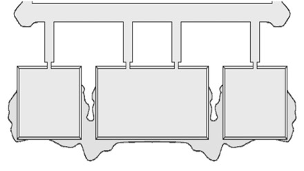
Flashes
Flashes are often seen near sealing faces, out of vent grooves, or down ejector pins. It appears as thin or sometimes thick sections of plastic where it would not be on a normal part. Flashing occurs when a thin layer of material is forced out of mold cavity at the parting line or ejector pin's location. This excess material remains attached to the molded article and normally has to be manually removed.
Factors causing flashes are given below –
- Insufficient viscosity of the melt
- Internal mold pressure too high
- Clamping force too high or too low
- Mold exceeding production tolerances damaged sealing faces
- Permissible gap width exceeded due to insufficient mold tightness

Weld lines
Weld lines are created when two or more melt flows fronts meet possibly causing a cosmetically visible line. It can also create a weakened area in the finished molded part especially with filled resins.
Factors causing weld line are –
- Slow injection speed
- Low melt temperature
- Low injection pressure
- Low mold temperature
- Improper venting in mold
- Poor material flow properties
- Excessive mold lubricant used
- The wrong type of gate or gate location

Weld lines
Sink marks
Sink marks are localized contractions or depressions on the surface of the molding. Sink marks appear as depression on the surface of a molded part. These depressions are typically very small; however, they are often quite visible because they reflect light in different directions to the part.

Sink marks
Blisters
- Surface blemish in the final part
- The trapped air can cause incomplete filling and packaging
- Air trapped in pockets get compressed, heats up and causes burn marks
- Air traps occur when converging flow fronts surround and trap an air bubble

Blisters
Jetting
- Jetting occurs when polymer melt is pushed at a high velocity through restrictive areas, such as the nozzle, runner, or gate, into open, thicker areas without forming contact with the mold
- Jetting originates at the gate, spreading over the entire part.
- The prominent inhomogeneous snake-like strands on the surface of molding
- When a cross-section of the molded part is increased rapidly in conjunction with high injection speeds
- Wrong position of the mold where melt fills the cavity from top to bottom

Jetting
Burn marks
- Burn marks or dieseling show up on the molded parts as charred or dark plastic caused by trapped gas and is usually accompanied by a distinctive burnt smell
- Diesel effect due to entrapped air at the end of the flow path and poor ventilation near the rib
- This is purely a venting problem, the trapped is compressed and gets heated to a high degree causing the burn on the plastic
- It can occur at blind holes, fillets, narrow ribs, near places where several flow fronts meet, end of flow paths etc.

Burn marks
Warpage
Warpage is the deviation of the molded part from its required shape. Warping part distortion is shown up as part being bowed, warped, bent or twisted beyond normal specification outlined on the drawing. Variation in mold temperature will cause components to warp.
Factors causing warpage are –
- Excessive feed
- More holding time
- Part ejected too hot
- Insufficient cooling time
- Too high injection pressure
- Poorly designed or operated cooling system
- Unbalanced gates on parts with more than one gate
- Variation in section thickness or contours of the screw
- Excessive area discharge or packed into the area around the gate
- Non-uniform mold temperature due to improper positioning if the cooling channels in the mold

Warpage
Streaks
Streaks are the prominent stretchy marks on the surface of the moldings.
Types of streaks—
- Charred streaks – Charred streaks due to excessive residence time in the plasticizing cylinder
- Moisture streaks – Streaks due to the excessive moisture content of the granules
- Air streaks – Streaks near ribs due to entrained and stretched air
- Coloured streaks – Color streaks due to incompatible masterbatch


Gloss differences
Factors causing the gloss difference are –
- Resins that are filled
- Molds that are textured
- Poorly polished mold surfaces
- Different cooling conditions. Shrinkage differences
- Stretching of already cooled areas e.g., due to warpage

Stress whitening
Cracking or crazing is caused by high internal stresses in the molded part or by an external force imposed upon the part. They can also be caused by an incompatible external chemical being applied to the finished parts. The cracks often don’t appear until days or weeks after the parts have been molded.

Hesitation
Hesitation is when the flow slows down or stops down along a particular flow path. If the plastic filling a cavity has the option of filing either a thin or a thick section, the plastic will tend to fill the thick section first as this route offers less resistance to flow. Hesitation can occur in ribs and in the thin sections of parts that have significant changes in wall thickness.
 .
. 
Hesitation
Overpacking
Overpacking is when extra material is compressed in one flow path while other flow paths are still filling.

Overpacking
Unbalance flow
Unbalanced flow is plastic completely filling some flow paths in the mold before other flow paths have filled. By altering the thickness of regions within the part, flow can be fastened or delayed in certain directions to help balance flow.
Also, see our Injection Molding Design Guide